Getting Started with the i.MX 8ULP EVK
本文档内容
-
Out of the Box
-
Embedded Linux®
-
Embedded Android™
-
MCUXpresso SDK

1. Out of the Box
The following section describes the steps to boot the i.MX 8ULP EVK.
Development kit contains:
- i.MX 8ULP EVK board
- Power supply: 5V/5A, Plug 2.1 mm x 5.5 mm
- Cable: Assembly, USB 3.0, Type-C Male to Type-A Male
- Cable: Assembly, USB 2.0, Type-A Male to Micro-B Male
- Software: Linux BSP image programmed in eMMC
- Quick start guide
1.1 Get Familiar with the Board


1.2 Boot from eMMC
The i.MX 8ULP EVK comes with a pre-built NXP Linux binary demo image flashed on the eMMC. Without modifying the binary inside, booting from the eMMC provides a default system with certain features for building other applications on top of Linux.
To understand more about NXP’s Embedded Linux®, continue reading the next sections.
1.3 Connect USB Debug Cable
Connect the micro-B end of the supplied USB cable into Debug UART port J13. Connect the other end of the cable to a
host computer.
If you are not sure about how to use a terminal application, try one of the following tutorials depending on the operating system of the host machine: Minicom Tutorial, Tera Term Tutorial, PuTTY Tutorial.
1.4 Connect the HDMI Cable
To see the user interface provided with the image binary, connect a monitor via the HDMI connector (J1).
1.5 Boot Switch Setup
The boot sequence is detailed in the i.MX 8ULP Reference Manual. In short, the boot modes of the i.MX boards are controlled by the boot configuration switches.
The switches set the boot media (depending on board, i.e. SD card, eMMC, NAND), the serial download protocol mode (SDP) or the value set on eFuses.
The SDP is also the fallback for the boot media, in other words, when the switches are configured to boot from SD card but the SD card slot is empty, or the SD card binary content is not bootable, the boot sequence continues to the SDP boot.

The following table lists the boot switch settings on the i.MX 8ULP EVK board. The same information can be found on i.MX 8ULP Reference Manual and on silkscreen on the board near the switches.
| Boot Mode | SW5
[D8-D1] |
| Boot from Fuses | 00xxxxxx |
| Serial Download | 01xxxxxx |
| A35-eMMC/M33-SPI NOR | 10000010 |
| Boot Mode | SW5
[D8-D1] |
| Single Boot-eMMC | 1000xx00 |
| Single Boot-SPI NOR | 1010xx00 |
| A35-eMMC/M33-SPI NOR (LP Boot) | 100000x1 |
| A35-SPI NOR/M33-SPI NOR (LP Boot) | 100111x1 |
1.6 Connect Power Supply
Connect the power supply cable to the power connector (baseboard P1). Power the board by flipping the switch
(SW10).
The processor starts executing from the on-chip ROM code. With the default boot switch setup, the code reads the fuses to define the media where it is expected to have a bootable image. After it finds a bootable image, the U-Boot execution should begin automatically.
Information is printed in the serial console for the Cortex®-A35. If you do not stop the U-Boot process, it continues to boot the kernel.
1.7 Congratulations Linux Has Booted
Once Linux is booted, login using the username root and no password.
# boot 1.8 NXP Demo Experience
The NXP Demo Experience is a user-friendly interface that allows you to launch preselected demonstrations included in the Linux Board Support Package (BSP) that NXP provides.
1.9 Demo Launcher
Graphical User Interface (GUI)
On boards where the NXP Demo Experience is available, an NXP Logo is displayed on the top left-hand corner of the screen. Users can start the demo launcher by clicking this logo.

After opening the program, users can launch demos using the following options shown in the figure below:
- To filter the list, select the icon on the left to expand the filter menu. From this menu, users can select a category or subcategory that filters the demos displayed in the launcher
- A scrollable list of all the demos supported on that EVK appears in this area with any filters applied. Clicking a demo in the launcher brings up information about the demo
- This area displays the name, categories and description of the demos
- Clicking Launch Demo launches the currently selected demo. A demo then can be force-quit by clicking the Stop Current Demo button in the launcher (appears once a demo is started)

To use this software, users need at a minimum:
- A supported NXP evaluation kit (EVK)
- A display output (MIPI DSI or HDMI)
- A connected mouse
1.10 Text User Interface (TUI)
Demos can also be launched from the command line through log-in into the board remotely or using the onboard serial debug console. Keep in mind that most demos still require a display to run successfully.
To start the text user interface, type the following command into the command line.
# demoexperience tui 
The interface can be navigated using the following keyboard inputs:
- Up and down arrow keys: Select a demo from the list on the left
- Enter key: Runs the selected demo
- Q key or Ctrl+C keys: Quit the interface
- H key: Opens the help menu
Demos can be closed by closing the demo onscreen or pressing the "Ctrl" and "C" keys at the same time.
2. Embedded Linux®
This section is applicable ONLY if attempting to load a Linux operating system on the board.
The i.MX Linux Board Support Package (BSP) is a collection of binary files, source code and support files that are used to boot an Embedded Linux image on a specific i.MX development platform.
Current releases of Linux binary demo files can be found on the i.MX Linux download page. Additional documentation is available in the i.MX Linux documentation bundle under the Linux sections of the i.MX Software and Development Tool.
2.1 Overview
Before the Linux OS kernel can boot on an i.MX board, the Linux kernel is loaded to a boot device (SD card, eMMC and so on) and the boot switches are set to boot that device.
There are various ways to download the Linux BSP image for different boards and boot devices.
For this getting started guide, only a few methods to transfer the Linux BSP image to an SD card are listed. Experienced Linux developers can explore other options.
2.2 Download an NXP Linux BSP Pre-Built Image
The latest pre-built images for the i.MX 8ULP EVK are available on the Linux download page under the most current version on Linux.
The pre-built NXP Linux binary demo image provides a typical system and basic set of features for using and evaluating the processor. Without modifying the system, the users can evaluate hardware interfaces, test SoC features and run user space applications.
When more flexibility is desired, an SD card can be loaded with individual components (boot loader, kernel, dtb file and rootfs
file) one-by-one or the .sdcard image is loaded and the individual parts are overwritten with the specific
components.
2.3 Burn NXP Linux BSP Image Using Universal Update Utility (UUU)
In addition to the connections from Out of the Box chapter, connect the baseboard USB0 to the host machine using the proper USB cable.
Turn off the board. Consult Boot switch setup and configure the board to boot on serial download protocol (SDP) mode.
Depending on the OS used in the host machine, the way to transfer the Linux BSP image onto an SD card can vary. Choose an option below for detailed instructions:
Linux
Install UUU on Linux Distro
Download the latest stable files from UUU GitHub page. If further assistance for UUU is needed, please refer to this extensive tutorial.
-
UUU libusb1(via apt-get or any other package manager)
Burn the NXP Linux BSP Image to the Board
By default, this procedure flashes the image to the eMMC flash. Check the UUU GitHub page for reference on how to flash the image to other devices.
Open a terminal application and change the directory to the location where UUU
and the latest Linux distribution for i.MX 8ULP EVK are located. Add execution permission to the
UUU file and execute it. UUU will wait for the USB device to connect.
$ chmod a+x uuu
$ sudo ./uuu <release package>.zipUUU will start to copy the images to the board.
When it finishes, turn off the board and consult. If further assistance is needed to configure the board to boot from emmc, please consult the Boot switch setup.
Windows
Install UUU on Windows
Download the latest stable files from UUU GitHub page. If further assistance for UUU is needed, please refer to this extensive tutorial.
-
UUU.exe - Serial USB drivers (depending on your board and Windows installation - check Windows Device Manager)
Burn the NXP Linux BSP Image to the Board
By default, this procedure flashes the image to the emmc flash. Check the UUU GitHub page for reference on how to flash the image to other devices.
Open the command prompt application and navigate to the directory where the UUU.exe file and the Linux
release for the i.MX 8ULP EVK are located.
UUU.exe <kernel_version>_images_<SOC>.zip
Turn on the board and
UUU will start to copy the images to the board.
When it finishes, turn off the board and consult. If further assistance with configuring the board to boot from emmc, please consult the Boot switch setup.
2.4 Burn the NXP Linux BSP Image to the Board
By default, this procedure flashes the image to the eMMC flash. Check the UUU GitHub page for reference on how to flash the image to other devices.
Open the command prompt application and navigate to the directory where the
uuu.exe file and the Linux release for the i.MX 8ULP EVK are located.
> uuu.exe <kernel_version>_images <SOC>.zip Turn on the board and UUU starts to copy the images to the board.
When it finishes, turn off the board and consult Boot switch setup to configure the board to boot from eMMC.
3. Embedded Android™
This section describes the boot process of loading the i.MX 8ULP EVK board with an Embedded Android system image and introduces how to build the software components that create your own system image. For details on building the Android platform, see this Android building guide .
The current release includes demo images, source code and documentation. These can also be found in Android OS for i.MX Applications Processor.
3.1 Overview
The storage devices on the development system (MMC/SD or NAND) must be programmed with the i.MX bootloader. The boot process determines which storage device to access based on the switch settings. When the boot loader is loaded and begins execution, the U-Boot environment space is then read to determine how to proceed with the boot process.
The images can come from pre-built release packages or be created from source code. Regardless of how you obtain them, all Android images contain the following components.
- U-Boot image:
u-boot.imx - Boot image:
boot.img - Android system root image:
system.img - Recovery root image:
recovery.img
For more information about the Android BSP, refer to the Android user guide.
3.2 Download NXP Android BSP Image
The pre-built NXP Android demo image provides a default system with certain features for evaluation. Without modifying the system, users can perform some basic operations and interact with the system to test hardware interfaces and develop software application in the user space.
The pre-built images from the package are categorized by boot device and put in the directory with the device name. The latest pre-built image files can be found in the Android section on the i.MX Software and Development Tools or on the demo images downloader link.
3.3 Burn NXP Android BSP Image Using UUU
In addition to the connections from the
Out of the Box
chapter, connect the
TYPE-C Port0 USB 3.0
to the host machine using the proper USB cable.
Turn off the board.
Consult the Boot switch setup and configure the board to boot on serial download protocol (SDP) mode.
Depending on the OS used in the host machine, the way to transfer the Android BSP image onto an eMMC can vary.
Once the image is copied to the board, turn off the board and consult Boot switch setup to configure the board to boot from eMMC.
4. MCUXpresso SDK
4.1 Overview
The MCUXpresso SDK is designed for the development of embedded applications for Cortex®-M33 standalone or collaborative use with the A cores. Along with the peripheral drivers, the MCUXpresso SDK provides an extensive and rich set of example applications covering everything from basic peripheral use case examples to demo applications. The MCUXpresso SDK also contains RTOS kernels and device stack and various other middleware to support rapid development.
This guide shows how to run the
m33_image.bin
demo provided by the
REL_2.14.0
release. For detailed information on MCUXpresso SDK and how to build and
deploy custom demos, please visit the
MCUXpresso SDK site
4.2 Run Applications Using imx-mkimage
This section describes how to run applications using the imx-mkimage tool and the pre-built m33_image.bin image for the i.MX 8ULP processor. The imx-mkimage tool generates a boot image container that bundles the different firmware images for i.MX 8ULP processors.
-
Following the steps from section 2.2, download the NXP Linux BSP pre-built image. The Cortex®-M33 SDK demo
images can be found in the imx_mcore_demos folder.
imx8ulp_m33_TCM_power_mode_switch.binis the default Cortex®-M33 reference demo image - If you have already loaded a NXP Linux BSP pre-built image in the eMMC device, you can skip this step
- Download the imx-mkimage tool from nxp-imx github
-
Get the following i.MX 8ULP firmware images from the Linux release package:
- EdgeLock firmware (
mx8ulpa2-ahab-container.img) - upower firmware (
upower.bin) - uboot-spl (
u-boot-spl.bin) - uboot (
u-boot.bin) - TF-A (
bl31.bin)
- EdgeLock firmware (
- Copy the firmware images to the
imx-mkimage/iMX8ULPfolder -
Copy imx8ulp_m33_TCM_power_mode_switch.bin image to the
imx-mkimage/iMX8ULPfolder and rename the binary to m33_image.bin -
imx-mkimage tool should contain the below binaries: imx-mkimage/iMX8ULP/
bl31.binm33_image.binmx8ulpa2-ahab-container.imgu-boot.binu-boot-spl.binupower.bin
-
Build the boot image container (flash.bin) Result boot image container is
make SOC=iMX8ULP REV=A2 flash_singleboot_m33iMX8ULP/flash.bin -
Set boot switches for serial download mode, consult Boot switch setup.
Connect the TYPE-C Port0 USB 3.0to the host machine using the proper USB cable. - Connect the DEBUG UART connector on the board to the PC through a USB cable. The Windows OS installs the USB driver automatically, and the Ubuntu OS will find the serial devices as well. See Connect USB debug cable section for more instructions on serial communication applications. Open a second terminal on the i.MX 8ULP EVK board’s fourth enumerated serial port. This is the Cortex-M33’s serial console. Set the speed to 115200 bit/s, data bits 8, 1 stop bit (115200, 8N1), no parity.
Minicom Tutorial
Serial Communication Console Setup
On the command prompt of the Linux host machine, run the following command to determine the port number:
$ ls /dev/ttyUSB* The smaller number is for Arm® Cortex®-A35 core and the bigger number is for Arm® Cortex®- M33 core.
Minicom
Use the following commands to install and run the serial communication program (minicom as an example):
- Install Minicom using Ubuntu package manager
- Launch Minicom using a console window using the port number determined earlier
- Configure Minicom as show in Figure 3
- The next step is to connect the display. Go to Connect the HDMI cable
$ sudo apt-get install minicom sudo minicom -s 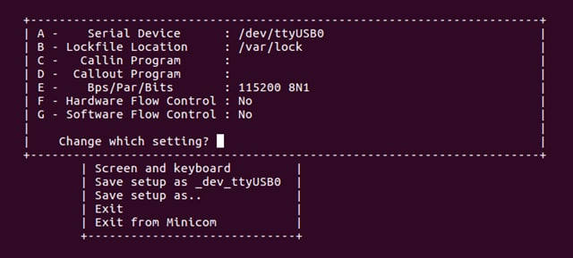
Tera Term Tutorial
Serial Communication Console Setup
The FTDI USB-serial chip on i.MX 8ULP enumerates two serial ports. Assume that the ports are COM9 and COM10. One port is for the
serial console communication from Arm® Cortex®-A35 core and the second port is for Arm®
Cortex®-M33 core. The serial-to-USB drivers are available at FTD Chip Drivers.
Teraterm
Teraterm is an open source terminal emulation application. This program displays the information sent from the NXP development platform’s virtual serial port.
- Download Tera Term. After the download, run the installer and then return to this webpage to continue
- Launch Tera Term. The first time it launches, it shows the following dialog. Select the serial option. Assuming that the board is plugged in, the
COMport should automatically populate in the list - Configure the serial port settings (using the COM port number identified earlier) to
115200baud rate,8data bits, no parity and1stop bit. To configure the serial port, go to Setup → Serial Port and change the settings - Verify that the connection is open. If connected, Tera Term shows something like below in its title bar
- The next step is to connect the display. Go to Connect the HDMI cable


Putty Tutorial
Serial Communication Console Setup
The FTDI USB-serial chip on i.MX 8ULP enumerates two serial ports. Assume that the ports are COM9 and COM10. One port is for the
serial console communication from Arm® Cortex®-A35 core and the second port is for Arm® Cortex®-M33 core. The serial-to-USB
drivers are available at FTD Chip Drivers.
Putty
PuTTY is a terminal-emulation application. This program displays the information sent from the NXP development platform’s virtual serial port.
- Download PuTTY. After the download, run the installer and then return to this webpage to continue
- Launch PuTTY by either double clicking on the executable file you downloaded or from the Start menu, depending on the type of download you selected
-
Configure In the window that launches. Select the Serial radio button and enter the
COMport number that you determined earlier. Also enter the baud rate, in this case115200 -
Click Open to open the serial connection. Assuming the board is connected and you entered the correct
COMport, the terminal window opens. If the configuration is not correct, PuTTY alerts you - The next step is to connect the display. Go to Connect the HDMI cable

本页内容
- 1.1
Get Familiar with the Board
- 1.2
Boot from eMMC
- 1.3
Connect USB Debug Cable
- 1.4
Connect the HDMI Cable
- 1.5
Boot Switch Setup
- 1.6
Connect Power Supply
- 1.7
Congratulations Linux Has Booted
- 1.8
NXP Demo Experience
- 1.9
Demo Launcher
- 1.10
Text User Interface (TUI)